The parallel port is unique in its abilities to maintain extremely
strict MIDI timing, better than USB, and far better than serial. With
some relatively simple circuitry, a 16x16 MIDI interface can be
constructed to attach to the parallel port, providing excellent timing
for less cost than a USB MIDI interface.
PCI-express parallel port cards are also available on the market,
for those of you who lack a parallel port, but crave its legendary
timing. If you have a laptop, build a desktop.
Some features may be optional -- one feature in particular is the 16x16 configuration. In particular, it consists of two separate boards -- the base 8x8 unit, and an optional 8x8 expansion board. Other configurations may also be possible (e.g., 4x4, 12x12), and unneeded inputs can be omitted freely to reduce component count.
At present, I recommend building the device onto a dedicated PCB -- I hope to provide step-by-step instructions in case you have never etched a PCB before. I'm looking into alternatives however -- it may be possible to build it onto stripboard (veroboard) or use point-to-point wiring.
Eventually, there will be easy-to-follow (hopefully!) documentation on how to build the device, along with a supplied driver for BeOS / Haiku (if anyone wants other platforms supported, you're encouraged to write drivers).
Since this is a PRE-ALPHA placeholder page, it's clearly not at that stage yet. At the moment, this documentation will be very nearly impossible for anyone to follow: it's for preview purposes only, for a technical audience.
Also note that because the design has changed so much, everything detailed from here onwards (except the "Updates" section below) is now irrelevant, until I update it.
The project has now reached the stage where complete schematics have been produced. However, it is important to note that these schematics have NEVER BEEN TESTED! If you happen to have the appropriate parts to hand, feel free to (solderless) breadboard the design as documented here, but I strongly advise against purchasing parts at this stage -- if something is later found wrong with the design, it could trigger sweeping design changes. Also note that no warranty whatsoever is provided, and you take full responsibility for anything that may occur, including (but not limited to) blowing up your PC and/or MIDI instruments.
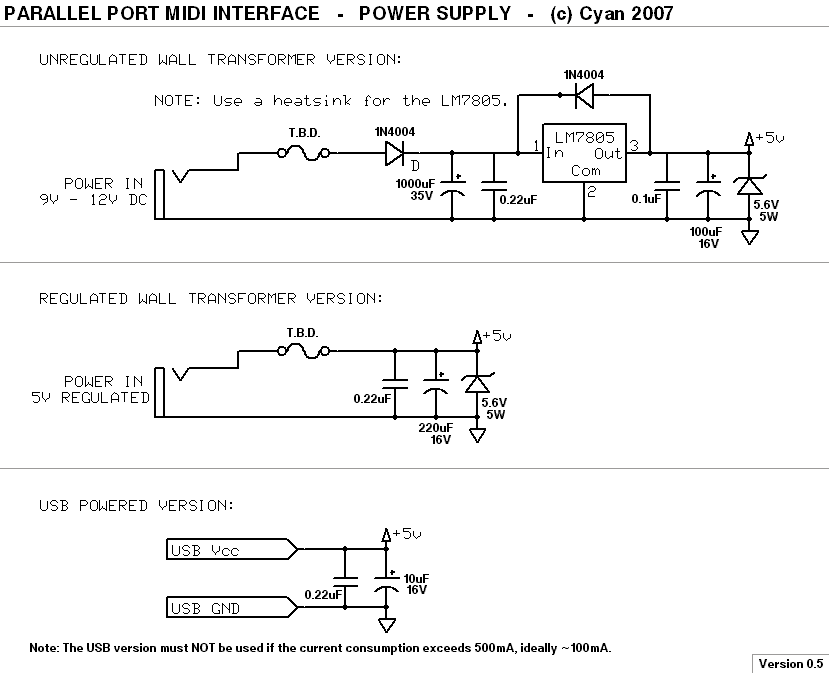
There are three different versions of the power supply, as shown
above. The first is intended to be used with a standard unregulated
9-12V DC wall transformer ("wall-wart", "AC adaptor", etc.) -- chances
are, you probably already have a suitable spare transformer somewhere.
You'll note the inclusion of a zener diode across the output of
the regulator -- this is to provide some last-ditch protection
in the event of a regulator failure. Given that an over-voltage
situation could damage the PC and up to 8 connected MIDI devices,
this should be considered essential.
This PSU design can also be used with an internal transformer to make a
self-contained rack unit. However, I strongly advise against
building the transformer into the case unless you're very experienced --
mains inside an unearthed metal case can lead to all kinds of deadly
experiences, and by putting a transformer inside the case, you run the
risk of creating hum -- both audible vibration, and induced magnetic
interference in nearby equipment.
The second version, which is much simpler, requires a regulated 5V wall
transformer -- these are usually SMPS units, much smaller than
unregulated wall transformers. If you're re-using a spare transformer,
make 100% certain that it's actually regulated -- measure the voltage
with no load, and with a 500mA load, to make sure it stays within
the range of 4.75 - 5.25V. Most, but not all SMPS wall transformers are.
Also, I strongly advise cutting the existing plug off, and fitting
your own non-standard power connector. This will avoid accidental
insertion of an incompatible supply, which may destroy the MIDI
interface, your PC, and all connected MIDI synthesizers. If you
do this, DO NOT re-use a mains connector for this purpose!
No matter how obvious it might seem at the time, a few years later
when you're rummaging around the tangled cables behind the rack
in the dark, a real mains cable will end up being plugged into the
device by accident. This will result in fire, complete equipment
destruction, and death. Don't even think about it!
However, providing you choose a non-standard, non-mains connector,
you should be fine. Tip: Avoid audio jacks because they short-circuit
briefly when they're inserted and removed.
The third version allows the device to be powered from a spare USB
port on your PC, rather than requiring its own dedicated power supply.
However, a word of warning: the USB specification requires that
"dumb" USB devices draw no more than 100mA of current ("intelligent"
devices are allowed to draw more). While the MIDI interface hasn't
been built yet (so a power consumption figure isn't known), there
is a strong possibility it may draw more than this -- perhaps
200-300mA. In most situations you can get away with drawing up to
500mA (many such USB devices are already on the market, such as
USB desk lamps, USB electric toothbrushes, etc.), but technically
it violates the specifications. Once the device has actually been
built and tested, I will be able to make a more informed
suggestion regarding this specific design.
Two important things to note regarding this design: 1) There is no
protection zener. The reasoning here is that if your PC's 5V rail
has gone significantly over-voltage, you're already seriously
stuffed, and you should've bought a PC PSU with over-voltage
protection. 2) The input electrolytic must be limited to 10uF to
avoid the USB 5V rail from sagging too much when you first connect
the device (this is a USB specification requirement). This does
make for rather lack-luster smoothing, but there's not much that
can be done about it. Just keep the USB cable length realistic
and it should work okay.
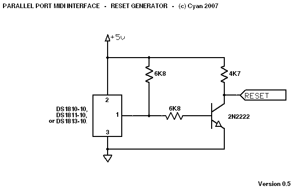
This circuit produces a reset pulse when you first turn the MIDI interface on. This ensures all the UART chips are reset correctly. It also handles correctly resetting the device if the power supply sags briefly -- e.g., a brownout occurs, or you turn the device off and back on again quickly. Without this feature, the device could start behaving erratically during a brownout, spraying random MIDI data out of all ports, etc.
I've decided to use a reset generator IC here -- any of the three listed ones should work fine, as should other similar devices. The IC keeps its output (pin 1) at logic 0 until the power supply voltage has been valid for at least 100ms.
There are some other possible designs that can be used here, without the need for special reset generator ICs. However, generally they're not as robust against brownouts. Unless anyone has trouble finding a reset generator IC, I won't go to the trouble of designing an alternative (inferior) circuit.
The 2N2222 can be replaced with almost any other NPN transistor if required.
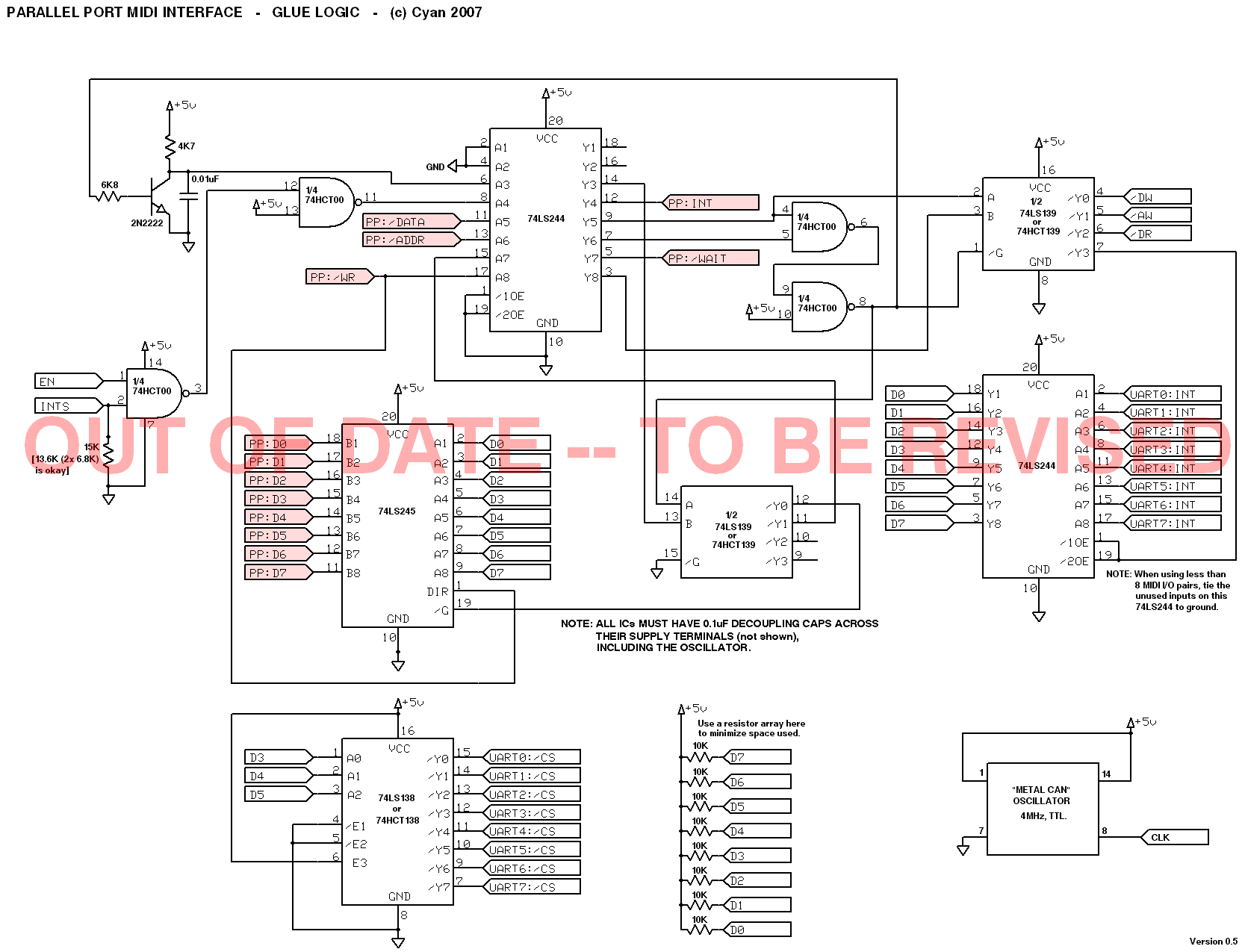
This is the core glue logic for the MIDI interface -- 6 ICs and a "metal can"-type oscillator.
I'm not even going to go into details here because it's too large -- either the schematic makes sense, or it doesn't (in which case wait until the final documentation is done!).
The pink connector markers ("PP:...") are the parallel port connections. Note that EPP mode is being used here, not SPP mode, hence the different signal names. It should work okay with EPP 1.7, EPP 1.9, or ECP+EPP selected in the BIOS.
Important note: Do not substitute logic families here (LS/HC/HCT)! As you can see, some of the chips are listed as LS / HCT, in which case you can use either, but for all other chips, use the exact same families as specified. This design has been a careful balancing act, and it will become unreliable (or fail to operate completely) if you use the wrong parts. This applies throughout the entire design, not just this schematic. Note: HC is NOT the same as HCT!
I haven't included any kind of EPP terminator in the above schematic.
In many cases this won't be required, but if you want to use long
cable runs, or have a particularly picky parallel port, you may want
to try adding a terminator: this consists of a 4K7 pullup on all
lines, and a 33 ohm resistor in series with each of the data lines
(D0 - D7). Adding a terminator may actually degrade the performance in
some cases however.
Whatever you do, though, make sure you ground ALL ground pins on
the parallel port connector, and use a proper IEEE1284-rated cable,
not some nasty old generic printer cable from an Amiga rig.
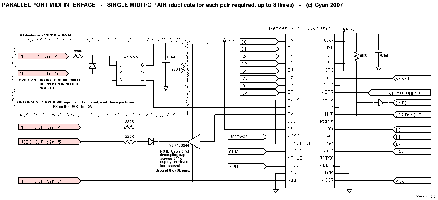
You'll need to build one of these for each MIDI input/output pair you need. Note that with some omissions, you can make an output-only module with fewer parts than a full I/O module.
One 74LS244 is shared between up to 8 modules (the maximum supported number) -- you don't need a separate '244 chip for each module.
Note regarding the /DTR pin on the UART: This should be connected only on the first module (#0). On all other modules, leave it unconnected.
Substituting parts: The 16C550A / 16C550B is also available in
dual / quad forms, which can save some board space if you can
get hold of them. Generally, the 16C650* and 16C750* should be
more or less compatible with the 16C550A/B, although this probably
won't be tested any time soon. The original (non-A) 16C550 should
be avoided, as should the 16C450*.
The Sharp PC900 optoisolator is sometimes hard to track down (in the
UK, Farnell stock them, along with the UARTs). If you can't get them,
there are some others which will work at a pinch -- I'll detail them
in the final document. Don't use any random optoisolator -- MIDI
requires the use of a very specific type of optoisolator.
Have fun!
- Cyan